Posts

Showing posts from March, 2017

Mosquito repeller

Image
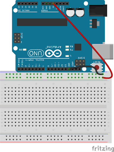
I nowadays mosquito is the huge problem and mosquito is also spreading many diseases and this DIY will really help you  Here is a list of the components and tools required Arduino Uno PCB Piezoelectric Disk Header Pins Wires Soldering Iron Soldering Lead do as shown in video   upload the code from here /* * this is an arduino project * for those who is getting sucked by mosquito */ int speaker = "9" ; //first let set the pin for pizo disk int frequency = "31000" ; /*now lets keep the frequency 31000hz * which irritate the mosquito */ void setup ( ) {   pinMode ( 9 , OUTPUT ) ; //set pin 9 as output } void loop ( ) {   tone ( speaker , frequency , 1000 ) ; //use tone command to set frequency   /*   * if you dont know about " tone "   * select tone and press   * Crtl + Shift + F   */    }

diy relay module

Image
I If you want a relay module and you are thinking that you will buy it online here is a link  Amazon.com : relay module but as you see it is expensive i will tell you a very cheap DIY material needed:- vero board/prototyping board relay 12v diode 40001 or 40007 bc558 transistor 9volt battery male header pin or simple wire for connecting step1:- place all the thing on the veroboard as shown in picture or in schematic or in video breadboard  view schematic picture step2:- connect signal to desired pin of arduino  and ground to ground pin of arduino and don't forget to connect 9volt battery  finished if it is not working check the diode position and transistor position and also see ground connections

simple car game

Image
simple car game this is a simple car game based on arduino and 16x2 lcd screen easy to make but take care for the wiring of lcd to arduino let's make material needed:- Arduino uno 16x2 lcd battery 10k potentiometer(2 pcs.) switch (needed for backlight) jumper wire breadbord(not necessary) instructions:- first connect arduino 5v & gnd to breadboard _________________________________________________________________________________________ connect lcd to arduino you should connect arduino to lcd connections are as follow from left to right lcd--->arduino 1--->gnd 2--->5v 3--->potentiometer(as shown in picture) 4--->D8 5--->gnd 6--->D9 7--->leave 8--->leave 9--->leave 10--->leave 11--->D6 12--->D5 13--->D4 14--->D3 15--->5v(using switch) 16--->gnd ________________________________________________________________________________________ connect potentiometer to A1 do as sho

pov display

Image
pov display here is an exciting project for you all pov display this project will float words in air and easy to made material needed:- Arduino nano (but can use any arduino) 5 leds 5 220 ohms resistor jumper wire battery vero/prototyping board switch (if needed) instructions:- first connect leds to vero/prototyping board connect the led to vero/prototyping board be careful that the led should be connected to digital pins 8,9,10,11,12 of arduino _________________________________________________________________________________________ after fitting leds to vero/prototyping board cut the excess board cut it by using a sharp knife or scissor. ________________________________________________________________________________________ upload the code on the arduino // how long each led stays on for int delayTime = 4 ; //how long between each int charBreak = 3 ; //how long to wait after the message is finished before it repeats int res